A strong oilfield case is not a brochure image. It is a decision path.
We show the site challenge, the molecule-to-electron architecture, the modular package boundary, the operation data layer and the commercial logic that makes the route worthwhile.
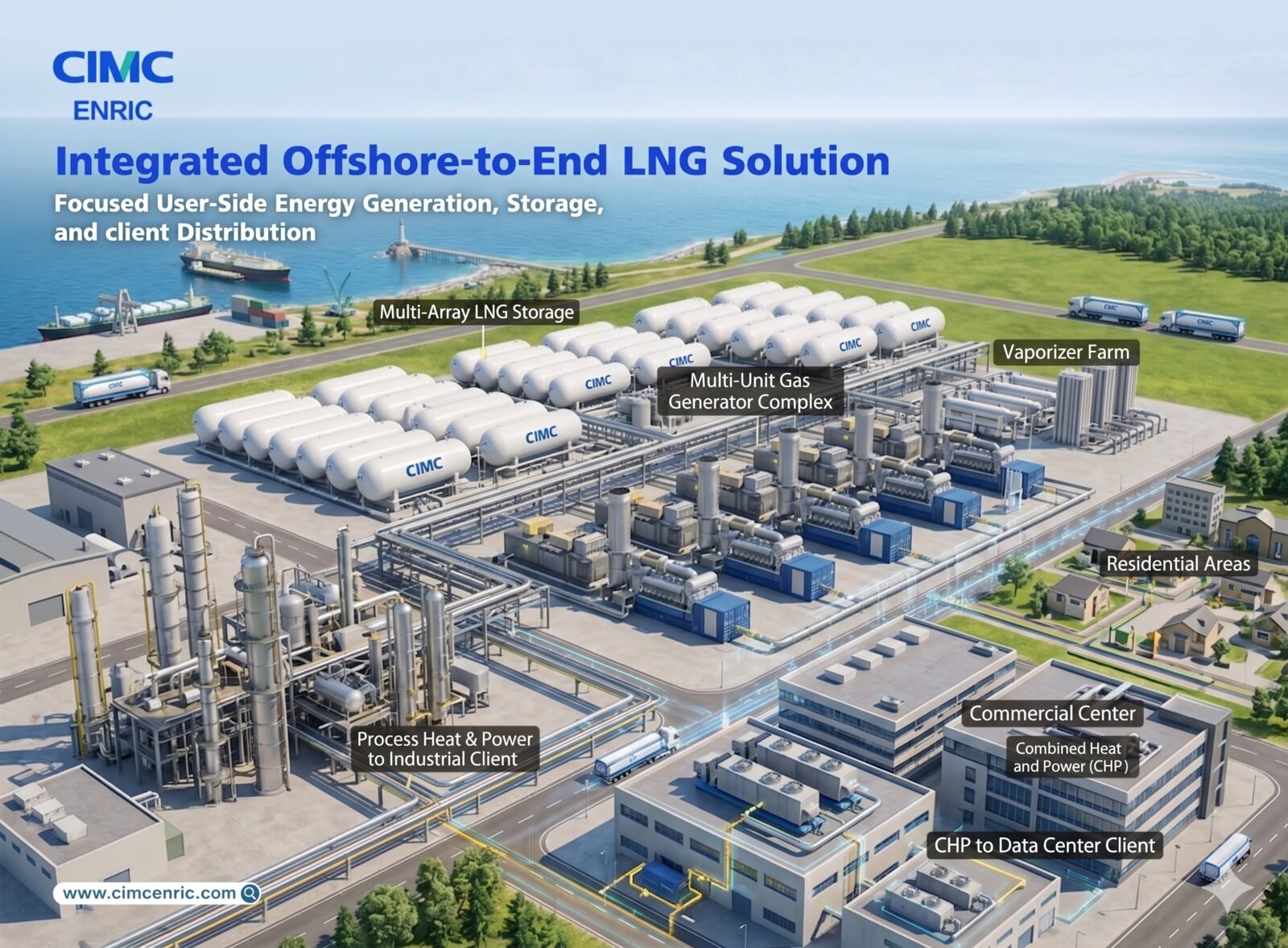
Oilfield energy starts with the fuel route and the load profile.
When gas, LNG or CNG is available, CIMC ENRIC can structure a gas-to-power system around storage, regasification, multi-unit generation and downstream electrical loads.
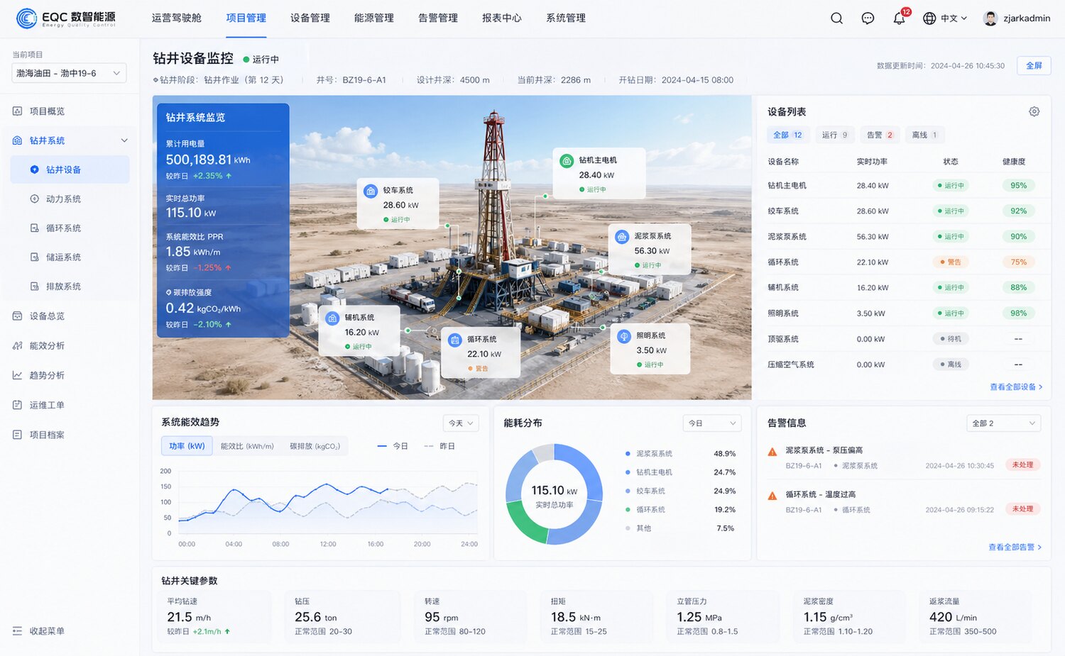
The case should show how operation is managed after commissioning.
The EQC monitoring interface gives the oilfield story a practical layer: equipment health, energy trends, emissions intensity, alarms and maintenance workflow.
| Project context | Wellsite equipment monitoring, drilling system load, equipment list, alarms and operating status. |
|---|---|
| Energy metrics | Cumulative electricity, real-time total power, specific energy use and carbon emissions intensity. |
| O&M loop | Health score, abnormal alerts, trend analysis and maintenance ticket management. |
The framework we will use as you send more oilfield material.
Each case page should read like a real project file: condition, design choice, delivery boundary and measured operation.
1. Site challenge
Remote field load, fuel logistics, diesel replacement pressure, weak grid, uptime and construction constraints.
2. Energy route
Gas, LNG, CNG or hybrid storage route selected according to resource quality and transportation condition.
3. System scope
Storage, regasification, generation, BESS, E-house, distribution, EMS and safety systems.
4. Modular delivery
Factory integration, transport, lifting, installation, commissioning and local service plan.
5. Operating data
Power, energy use, carbon intensity, equipment health, alarms, maintenance and lifecycle improvement.
6. Business result
LCOE comparison, fuel saving, reliability improvement, timeline advantage and asset scalability.
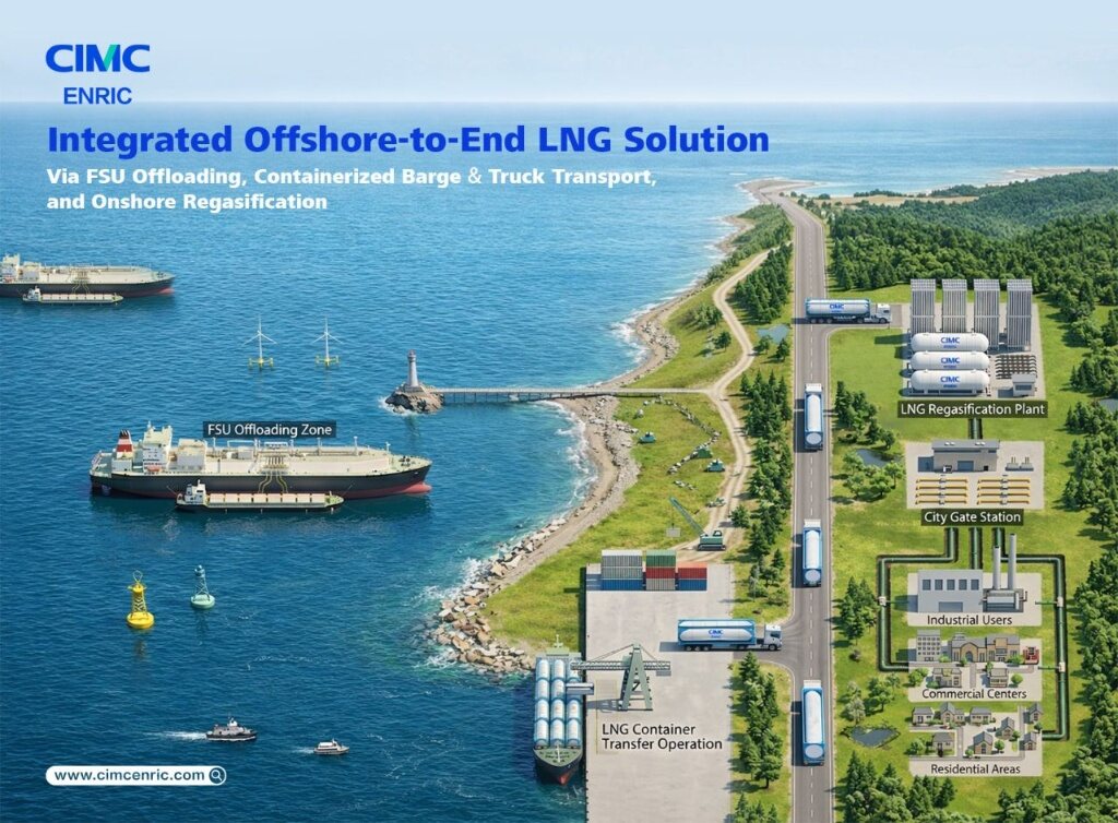
Future oilfield cases can branch by fuel route.
As more material arrives, this case page can split into offshore LNG supply, associated-gas utilization, mobile CNG logistics, drilling power optimization and field camp microgrids.